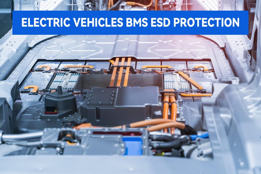
BMS is the abbreviation for Battery Management System, a core component of new energy vehicles (NEVs). It is a complex system designed to monitor and manage battery pack states, intelligently supervising and maintaining individual battery cells to prevent overcharge and over-discharge conditions, extend battery service life, and ensure safe, efficient operation through continuous state monitoring.
Primary Functions of BMS
- (1) Battery Parameter Monitoring
- (2) State-of-Charge (SOC) Estimation
- (3) Cell Balancing Management
- (4) Fault Diagnosis and Protection
- (5) Charge and Discharge Management
- (6) Thermal Management
- (7) Communication and Data Logging
- (8) Remote Monitoring
BMS System Architecture
- Main Board (Master Control Unit): Aggregates sampling data from all slave boards, controls relay actuation within the Battery Disconnect Unit (BDU), implements real-time monitoring of battery parameters, and communicates with the vehicle via low-voltage interfaces.
- Slave Board (Cell Monitoring Unit): Monitors module-level voltage and temperature data, transmitting acquired information to the main board.
- BDU (Battery Disconnect Unit): Comprises pre-charge circuitry, main positive relay, main negative relay, and fast-charge relay.
- High-Voltage Control Board: Implements real-time monitoring of battery pack voltage and current, incorporating pre-charge detection and insulation resistance monitoring functions.
Each functional module within the BMS is interconnected via Controller Area Network (CAN) bus. CAN is a serial communication network enabling distributed real-time control. The CAN circuit consists of functional circuitry, microcontroller, CAN controller, and CAN transceiver, with the CAN transceiver responsible for conversion between logic-level signals and physical bus signals. The CAN bus infrastructure also incorporates RS-232 interfaces, which provide full-duplex serial communication enabling bidirectional data transmission with external devices.
Given the complexity of this electronic system, signal and power lines are highly susceptible to ESD transients during vehicle start-up and operation, potentially inducing delayed or interrupted command responses. Consequently, ESD protection for BMS architectures is critical. For CAN transceiver interfaces, the 6AJ24A is specified; for RS communication interfaces, the SMAJ12A is employed.
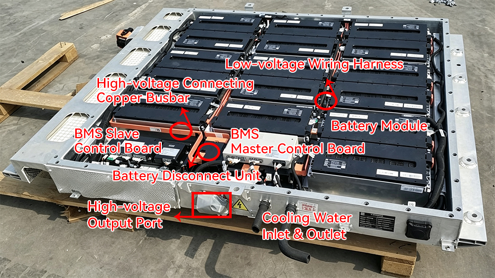
Figure 1 BMS in Battery Pack
–
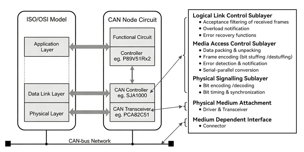
Figure 2 CAN Structure
–
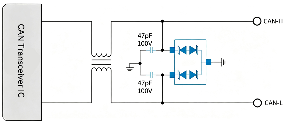
Figure 3 ESD Protection for CAN Lines
–
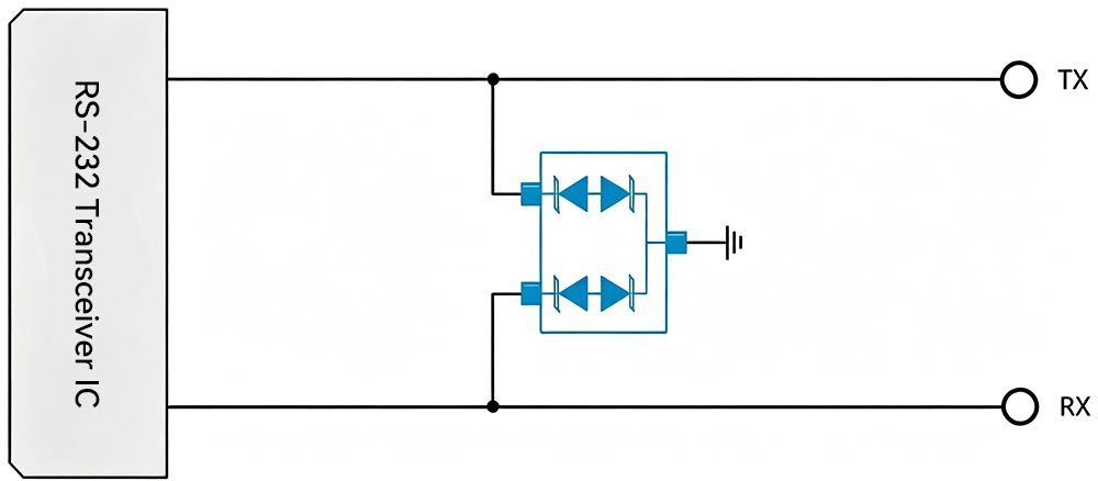
Figure 4 ESD Protection for RS Communication Interface
–
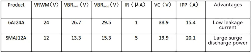
JY Electronics’s Product Parameter Tables
The foregoing describes ESD protection for BMS control domains. Within the BMS electrical architecture, motor drive employs active gate drivers to enhance efficiency and reliability under high-frequency, high-power operation. On-board charging involves external-facing charge ports, while instrument clusters are exposed to environmental contact—all requiring robust ESD protection for reliable operation under harsh automotive conditions.
For motor drive applications, the TT1211MB is specified. On-board charging incorporates USB 2.0, Type-C, and wireless interfaces; taking USB 2.0 as representative, the receptacle features four pins: VBUS, D+, and D-. For VBUS protection, the TS0511LE is employed; for D+ and D-, the TT0521SB is specified. Typical instrument clusters include tachometer, speedometer, fuel gauge, coolant temperature gauge, and oil pressure gauge—each exhibiting distinct current-voltage transmission characteristics, yet all requiring stable output and low power consumption. Protection devices must therefore exhibit low leakage current and rapid transient response. Taking the tachometer as representative, the TT1211MB is specified.
–
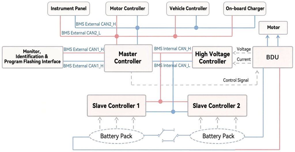
Figure 5 BMS Electrical Architecture
–
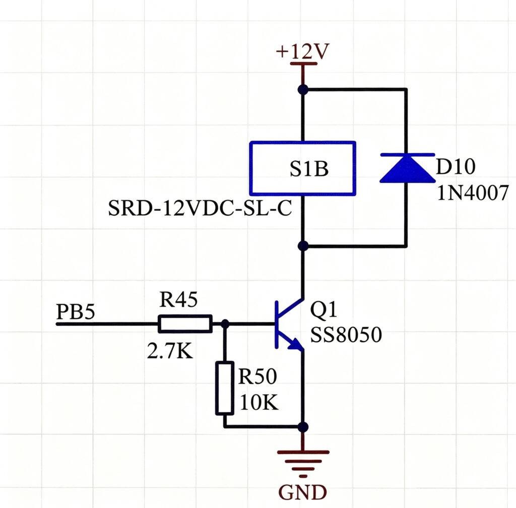
Figure 6 ESD Protection for Motor Drive
–

Figure 7 USB 2.0 Pin Configuration
–
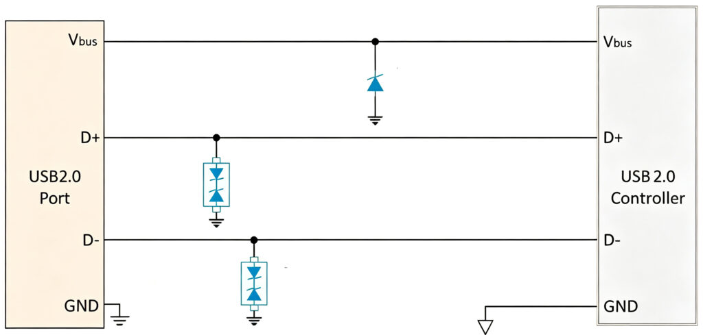
Figure 8 ESD Protection for USB 2.0
–
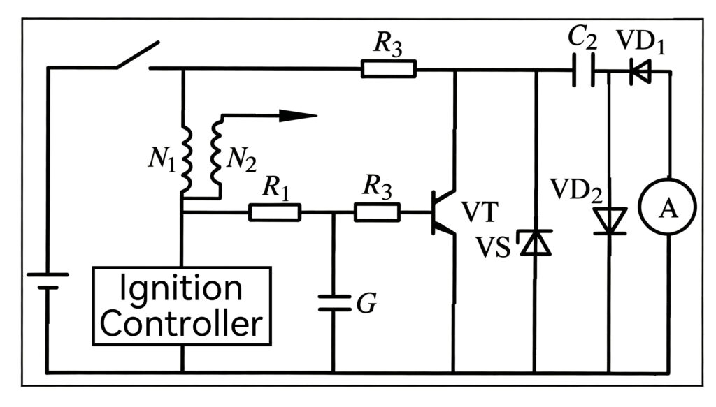
Figure 9 ESD Protection for Tachometer
–
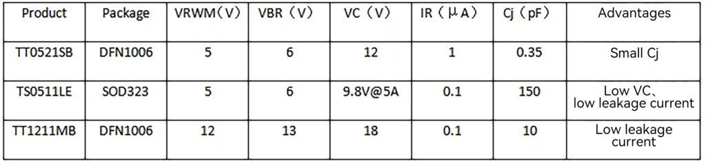
JY Electronics’s Product Parameter TablesIn
Summary, ESD protection within automotive BMS is of critical importance and warrants rigorous attention. As vehicle functionality continues to expand, electrical architectures will grow increasingly complex, incorporating greater numbers of electronic components and correspondingly diverse ESD protection requirements. Future ESD protection devices must evolve toward greater diversification to satisfy application-specific demands across heterogeneous automotive subsystems.
……………………………………………………………………Company Profile……………………………………………………………………
JY Electronics serves a global customer base across the automotive, industrial & power, computing, consumer, and mobile & wearables industries. Our extensive product portfolio includes Schottky diodes, TVS and ESD protection devices, MOSFETs, LDOs, power ICs, battery protection & segment driver ICs, industrial & automotive-grade sensors, high-side switches (HSD), current sensors, and automotive switch input chips. We are committed to continuous innovation, delivering high-quality products that empower our customers to develop energy-efficient and sustainable solutions.
For samples or a quotation, please contact us at market@jy-electronics.com.cn.