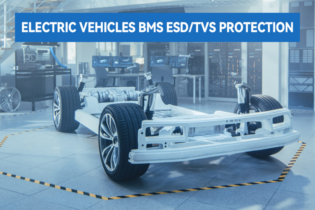
The automotive Battery Management System (BMS) is employed to manage and monitor vehicle batteries—particularly traction batteries in electric vehicles (EVs)—ensuring safe, reliable, and efficient operation while extending battery service life. The BMS is regarded as the battery’s “safety brain,” with its stability directly determining vehicle-level safety and longevity.
Notably, electromagnetic interference (EMI) protection deficiencies account for 80% of BMS field failures. Specifically, electrostatic discharge (ESD) and electrical overstress (EOS) surge overvoltage represent latent threats capable of inducing dielectric breakdown in integrated circuits, disrupting communication buses, and potentially triggering thermal runaway in battery packs. This technical analysis examines TVS and ESD protection device selection methodologies for critical BMS nodes, framed within representative system architectures.
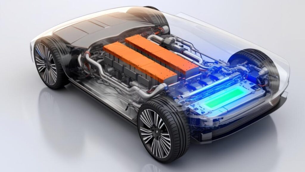
Overview of Automotive BMS Operating Principles
Automotive BMS architectures are categorized into two primary types: wired BMS and wireless BMS.
Wired BMS represents the dominant architecture in current automotive applications. As illustrated in Figure 1, the battery monitoring integrated circuit (BMIC) acquires real-time measurements of cell voltage, current, and temperature across multiple channels—for instance, an EV battery pack comprising 96 series-connected cells requires a BMIC with corresponding channel count to capture per-cell voltage data, thereby enabling comprehensive state-of-charge (SOC) and state-of-health (SOH) estimation. The BMIC converts these analog measurements to digital signals, performs initial data conditioning (including cell balancing algorithms and fault detection), and transmits processed data to a downstream microcontroller unit (MCU). The MCU interfaces with other electronic control units (ECUs) via automotive communication protocols, typically Controller Area Network (CAN) or Local Interconnect Network (LIN). Wired BMS architectures exhibit robust immunity to electromagnetic interference and stable transmission characteristics, satisfying the high-reliability requirements of automotive high-voltage, high-EMI environments. However, these systems incur complexity in wiring harness design and elevated lifecycle maintenance costs.
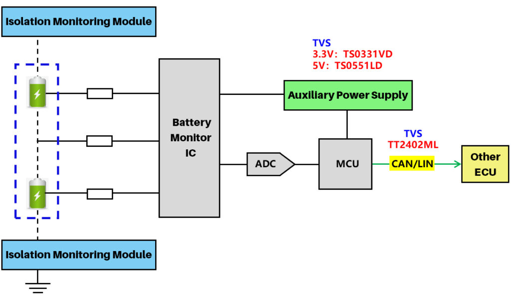
Figure 1. Wired BMS Architecture
Wireless BMS has emerged as a novel architecture in recent years, typically employing Bluetooth Low Energy (BLE) or proprietary wireless protocols (antenna-based) for intra-module data acquisition. As depicted in Figure 2, wireless cell monitoring units (CMUs) acquire per-cell voltage, current, and temperature data, transmitting this information wirelessly to a central battery monitoring IC. The BMIC performs analog-to-digital conversion, preliminary signal processing, and fault diagnostics, subsequently forwarding conditioned data to an MCU. The MCU communicates with other ECUs via standard automotive interfaces such as CAN or RS-485.
Additionally, the gate driver depicted controls MOSFET switching elements for charge/discharge path management—this functionality may alternatively be implemented using JY Electronics’ eFuse product JYH50030A, replacing the conventional “MOSFET switch + gate driver” topology. Compared with traditional wired architectures, wireless BMS offers primary advantages in reduced wiring harness complexity and enhanced layout flexibility. However, limitations imposed by automotive electromagnetic interference and signal obstruction (multipath fading, body shielding) currently restrict deployment to auxiliary monitoring roles or specific application scenarios.
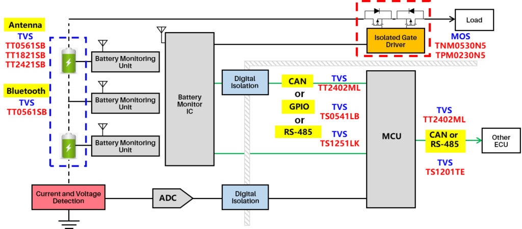
Figure 2. Wireless BMS Architecture
Contemporary automotive BMS architecture evolution is trending toward a hybrid paradigm: wired backbone with wireless augmentation. This approach preserves the high reliability of wired communication for critical safety paths while leveraging localized wireless acquisition to simplify module-internal interconnect, achieving an optimal balance between system robustness and design flexibility.
Why BMS Protection Constitutes a Critical Non-Negotiable for OEMs
For new energy vehicles (NEVs), BMS protection design is not merely value-added enhancement—it is a fundamental safety imperative:
Regulatory Mandate: National Standard GB 38031 (Technical Specifications for Power Battery Safety of Electric Vehicles) explicitly requires ESD and surge immunity compliance for BMS subsystems. Non-conformance constitutes a market access barrier, preventing vehicle type approval and commercial launch.
Safety Criticality: A prominent NEV OEM experienced a high-speed battery pack false-disconnect event attributable to BMS communication interface surge protection failure, resulting in large-scale vehicle recall and significant brand reputation damage.
Cost Impact: Core BMS ICs exceed RMB 100 per unit. ESD-induced dielectric damage triggering batch repair incidents can incur per-vehicle losses reaching thousands of RMB, excluding warranty liability and customer satisfaction degradation.
Performance Assurance: Inadequate protection at high-frequency interfaces (Bluetooth, RF antenna) introduces insertion loss and impedance mismatch, directly degrading telematics functionality and user experience metrics.
BMS protection investment functions as insurance against recall costs, brand equity erosion, and user safety liability—yielding quantifiable risk-adjusted returns.
Comprehensive BMS Protection Scenario Analysis
System-level analysis identifies four primary vulnerability zones within BMS architectures:
Wireless Communication Zone: Bluetooth and antenna interfaces operate at RF frequencies (2.4 GHz ISM band, sub-6 GHz 5G NR) with high susceptibility to electromagnetic interference. Recommended protection: TT0561SB / TT1821SB / TT2421SB—covering operating voltages of 5V, 18V, and 24V respectively, with junction capacitance of merely 0.16–0.25 pF and superior capacitance linearity (voltage coefficient <1.05). These characteristics ensure minimal signal integrity degradation while providing robust immunity to automotive electromagnetic stressors.
Bus Communication Zone: CAN, LIN, GPIO, and RS-485 interfaces facilitate multi-device interaction across extended cable harnesses, introducing vulnerability to coupled noise, surge transients (load dump, alternator field decay), and ESD events. JY Electronics recommends TT2402ML / TS1251LK / TS1201TE / TS0541LB, with selection contingent upon specific protocol requirements: CAN bus differential protection (TT2402ML, 24V reverse standoff), LIN single-wire protection (TS1251LK, 12V bus-compliant), RS-485 transceiver protection (TS1201TE, 15V working voltage), and general-purpose I/O protection (TS0541LB, 5V logic-level).
Power Delivery Zone: Supply rail transients—induced by load dump events (ISO 7637-2 Pulse 5a/5b), inductive switching, and load step transitions—require precision-matched protection. TS0331VD (3.3V rail, 18V clamping) and TS0551LD (5V rail, 24V clamping) provide sub-nanosecond response with tight voltage clamping, preventing overvoltage damage to downstream DC-DC converters and LDO regulators.
Key parameters for recommended devices are summarized below:
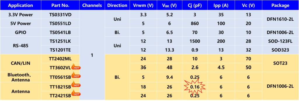
Figure 3. JY Electronics ESD & TVS Selection Guide for Automotive BMS Applications
Power Drive Zone:
Option 1: Isolated Gate-Driven MOSFET—high-current operation induces thermal stress exceeding Safe Operating Area (SOA) limits. JY Electronics recommends TNM0530N5 (N-channel, 30V, 5.0 mΩ max) and TPM0230N5 (P-channel, 20V, 3.0 mΩ max) in PDFN5×6-8L thermally enhanced packages. Thermal resistance RθJA is reduced by 30% versus conventional SOP-8, with low R_DS(on) minimizing conduction losses—optimal for BMS charge/discharge path switching.
Option 2: eFuse Integration—JYH50030A replaces discrete “gate driver + MOSFET” implementations with a monolithic intelligent high-side power switch. Packaged in TOLL-8L with ultra-low on-resistance of 3.0 mΩ at 25°C, this single-channel device integrates overcurrent protection, overtemperature shutdown, and reverse polarity protection with diagnostic feedback (fault flag output). Specifically architected for high-current BMS load switching applications.
Key parameters for recommended power devices are summarized below:
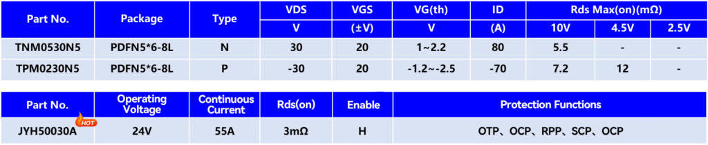
Figure 4. JY Electronics MOSFET and eFuse Selection Guide for Automotive BMS Applications
BMS protection design is not a matter of indiscriminate component accumulation—it demands systematic integration of architecture constraints, signal integrity requirements, and environmental stressor analysis to achieve precise matching of TVS/ESD protection devices. A rigorously engineered protection strategy enhances system reliability while enabling OEMs to accelerate EMC compliance certification (CISPR 25, ISO 11452) and reduce time-to-market.
……………………………………………………………………Company Profile……………………………………………………………………
JY Electronics serves a global customer base across the automotive, industrial & power, computing, consumer, and mobile & wearables industries. Our extensive product portfolio includes Schottky diodes, TVS and ESD protection devices, MOSFETs, LDOs, power ICs, battery protection & segment driver ICs, industrial & automotive-grade sensors, high-side switches (HSD), current sensors, and automotive switch input chips. We are committed to continuous innovation, delivering high-quality products that empower our customers to develop energy-efficient and sustainable solutions.
For samples or a quotation, please contact us at market@jy-electronics.com.cn.