As consumer demand for faster and more reliable data transfer increases, manufacturers face stricter requirements for ESD protection in high-speed signal interfaces. Electrostatic discharge poses significant risks to electronic products, including:
1、Data Corruption or Loss: ESD can disrupt signal transmission, leading to data errors and loss, thereby compromising product functionality and performance.
2、Component Damage: ESD-induced voltage spikes can exceed the tolerance of sensitive ICs and circuits, potentially damaging high-speed interfaces or circuit boards and rendering the device inoperative.
Therefore, robust ESD protection is crucial for safeguarding the functional integrity of electronic products. ESD suppressors (ESD diodes) or transient voltage suppressors (TVS diodes) are essential protective devices.
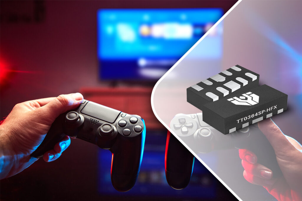
JY Electronics Recommended Protection Solution: TT0364SP-HFx
JY Electronics introduces the TT0364SP-HFx, a dedicated ESD protection solution for high-speed signal interfaces such as USB 3.1, USB 3.2, Thunderbolt, and HDMI 2.0. This device offers the following key advantages:
1、Cost-Effective Single-Core Solution: Streamlines design and reduces BOM costs.
2、Ultra-Low Capacitance: 0.37 pF (at VR=0V, f = 1MHz) ensures signal integrity in high-speed data transmission.
3、Low Clamping Voltage: 3.2V (@ 5.5A IPP under 8/20μs waveform testing) achieved through our patented deep snapback technology, offering superior protection compared to conventional ESD diodes.
4、High ESD Withstand Capability: Complies with IEC 61000-4-2, capable of withstanding ±10kV contact and ±10kV air discharge.
5、Compact Design: Four-channel integrated array in a DFN2510-10L package minimizes PCB footprint and reduces overall cost.
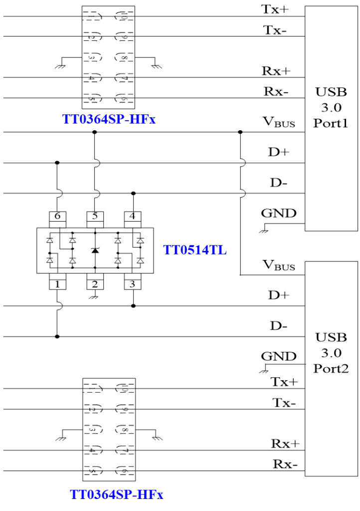
JY Electronics Selected ESD Protection Solution
ESD Performance Parameter Table

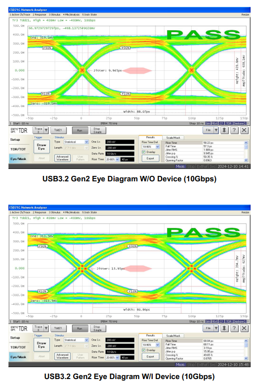
Eye Diagram Test Curves
Layout Considerations:
1、Proximity: Place ESD protection devices as close as possible to I/O connectors to minimize ESD current paths and maximize protection effectiveness.
2、Routing: Use rounded corners or 45-degree angles for PCB traces to avoid reflections caused by sharp bends.
3、Differential Traces: Maintain matched trace lengths between positive and negative lines of differential data channels to prevent common-mode noise and impedance mismatch.